Engineering
SERVICES
Engineering
Nordic Crane Engineering has a number of engineers with substantial knowledge and broad experience. Many of our projects require careful planning and proper documentation, and we adhere to numerous strict requirements for safety and quality. Using advanced tools, we can simulate the entire project in advance and consequently operate safely, securely and with outstanding quality.

Accuracy
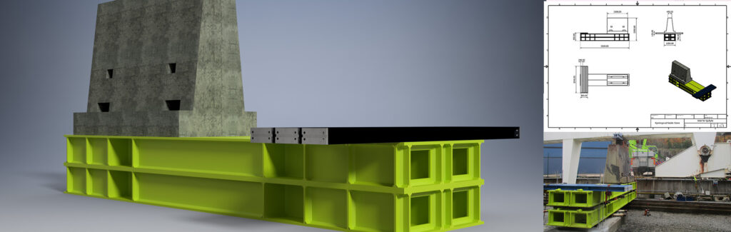
Through 2D- and 3D- modelling in addition to advanced calculation tools, Nordic Crane Engineering can create lifting plans, calculate lifting equipment, check ground pressure, and place any crane to be used on millimeter-accurate maps and drawings.
We use several different tools
There are many factors that can create challenges when executing a lift or a transfer. Everything from weight, large radii and height, but also confined spaces, narrow lifting angles and weak surfaces can complicate working conditions. We use a number of different tools ranging from 3D models, mathematical calculations and simulations to be able to predict and show with accuracy how the assignment will be carried out.
Services that Engineering can provide:
- Calculation: General calculation-reports such as ballast calculations or beam-calculations.
- General Arrangement: Outline drawing of an operation that shows concise method.
- Jacking Arrangement: Arrangement for placing jacks under modules and how the jacks should stand on the supports.
- Lift Plan: Lifting plan that shows crane configuration, key figures and shows where the crane should stand.
- Manual: Method Statement that includes everything from equipment, method, risk analysis, contact persons, location, drawings, etc. in detail.
- Rigging Arrangement: As a rule, supplement to the Lift Plan. Detailed drawing showing exactly which rigging equipment to use, from the hook down to the structure.
- Transport Arrangement: Standard SPMT drawing that should show the top view, side view and end view of the structure with the SPMTs below it. The drawing should show exactly how the SPMTs should stand in relation to the module and supports. The drawing must also include how the hydraulic groups should be displaying the key figures from the calculations (pressure, shaft load, ground pressure, stability, etc.).
- Transport Route: Outline drawing of the site showing route from start to finish. The drawing must be clear to the operator so that one can understand the road and inspect the route before the actual transport. You as a customer can use such drawings to ensure that the route is ready and, not least, approved for the cargo applied during transport.
- Weighing Arrangement: This is a drawing that will show where the loading-cells should be in relation to the module. Should also show great detail in how the structure should be weighed (jacks under/on top of the cells, possibly with crane/SPMT, etc.).